The hardware essentials: what the parts are, how to power and charge it, how to aim it, and how to swap the battery. For the on-screen interface, see the Screen Guide. For the files on the device, see Your Files on a PC.
Overview
Device at a glance
A robust, lightweight handheld with a 4-inch touchscreen, a single power button on the back, a USB-C port on the bottom for charging and data, and a trigger on the handle that takes a measurement.
Figure 1 — The Helios, in 3D. Drag to turn it, or use the view buttons below. The nameplate shows an example serial number, not yours.
The parts
Touchscreen — live camera view, readings, and every setting
Power button — on the back; a short press switches on, a two-second hold switches off
Trigger — pull and hold to take a reading, release to save it
Pyrometer window — the largest of the four, the infrared channel that measures temperature
Camera — the smaller window above the measuring one, giving the live view on screen
Targeting lasers — two small windows, one either side, projecting the green dots
Protective cover — covers the camera, laser and measuring windows when the device is not in use
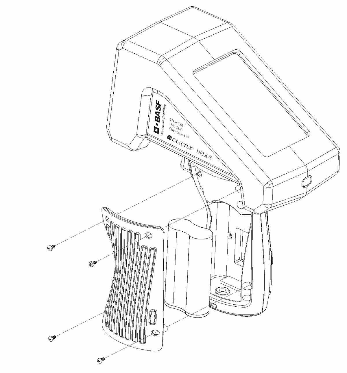
Battery cover — four screws, and the battery is replaceable by the user
USB-C port and charging light — on the bottom face, near the power button
Lanyard loop — for a wrist or shoulder strap
Power
Powering on and off
Power on
Press the power button on the back and let go. This is a short press, not a hold.
The green targeting lasers switch on first. That is the device confirming it is starting up.
The screen stays dark for up to ten seconds while the device starts, then lights up with the live camera view. The targeting lasers go out as the screen lights.
Holding the button down for longer than about five seconds does not start the device.
Power off
Press and hold the power button for about two seconds. The screen goes black.
Let go once the screen is black. The device is off.
The device can also be set to turn off automatically — configure this in Power Settings.
Connecting the charger or fitting the battery does not switch the device on. A plugged-in device that stays dark is normal — press the power button to start it. If it still does not start, charge the device and try again.
Charging
How to charge
Locate the USB-C port at the bottom of the device and connect the supplied USB-C cable.
Plug the other end into a certified USB power adapter or computer port.
While charging, the battery indicator shows a charging symbol and the exact battery percentage.
A 100 % indicator means fully charged. The device may stay connected to power without risk of overcharging.
LED indicator
A steady red LED indicates the battery is charged.
A flashing LED indicates the battery is actively charging.
Optics
Optics and sighting
The Helios gives you target vision through a camera mounted above the pyrometer’s optical axis, with green targeting lasers set symmetrically to its left and right. All four optical axes are aligned at manufacture to be parallel. The camera and pyrometer focus are fixed.
Key facts
Camera field of view: 30°
Camera window: 29 mm above the measuring window
Laser windows: 25 mm either side of the measuring window
Laser dots on the target: 50 mm apart at any distance
Pyrometer spot size: ~20 mm diameter at 1–2 m, opening to 30 mm at 3 m
Spectral response: 1 µm
Laser: Class II, < 1 mW
Spot size vs. distance
Target distance
Collection area
1 m (3.3 ft)
20 mm (0.8 in)
2 m (6.6 ft)
20 mm (0.8 in)
3 m (9.8 ft)
30 mm (1.2 in)
5 m (16.4 ft)
60 mm (2.4 in)
10 m (32.8 ft)
140 mm (5.5 in)
Where the device is measuring
Aim the Helios with the two green laser dots on the target, not with the screen. The spot the device measures always lies exactly halfway between the two dots, so putting one dot either side of the area you want to read puts the measurement on it.
The camera sits a short distance above the axis the device measures along. Because of that gap, the measured spot is not in the middle of the picture. It sits on the centre line, below the middle, and it climbs towards the middle as the target gets farther away. The device cannot tell how far away the target is, so the mark on the screen cannot follow the spot. Instead it shows the whole path the spot moves along.
The measured spot is always on the centre line of the picture, below the middle.
The farther away the target, the closer to the middle the spot sits. It never reaches the middle.
The two laser dots move the same way. Farther away, they sit higher and closer together.
Wherever the dots are, the measured spot is on the centre line between them, a little above the halfway point.
The two dots stay the same distance apart on the target whatever the range, so they also work as a size reference.
Figure 2 — Why the measured spot moves. The camera and the measuring axis stay a fixed distance apart at every distance. Not to scale.
Figure 3 — Where the measured spot lands in the picture, over a bright target. Choose a target distance. The movement is shown enlarged; the three positions are correct relative to each other. 1 m = 3.3 ft, 2 m = 6.6 ft, 3 m = 9.8 ft.
Choosing a reticle
The mark drawn in the middle of the screen can be changed under Settings, then Reticle. The device remembers your choice when it is switched off.
Standard — a vertical line crossed by three horizontal bars, forming a scale. The closer the target, the lower on the line the measured spot sits, and the wider apart the two laser dots are. The top of the mark sits on the centre of the picture, which the spot moves towards as the target gets farther away but never reaches.
Keyhole — an open outline in the same position. It leaves the target itself uncovered.
Alignment — a service view, not a normal aiming mark. It magnifies the camera image about two times, holds the aiming laser on, and draws a red cross over the whole screen. Use it to check that the laser and the camera still agree, then switch back to Standard or Keyhole for normal work.
Standard
Keyhole
Alignment
Figure 4 — The three reticles you can choose from. Each mark has a black core with a white edge, so it stays visible whether the target is glowing hot or in shadow. Each tile shows both. The lowest bar of the Standard mark runs to the edge, as it does on the device.
Maintenance
Replacing the battery
The battery is a commonly available Li-ion pack and is user-serviceable. It’s accessed through the battery cover on the handle grip.
Figure 5 — Battery replacement (exploded view)
Remove the 4× M2 screws on the battery cover.
Remove the battery and fit the replacement pack.
Seat the battery connector into its pocket — insert it without compression between the battery and the case.
Caution: ensure the battery connector is replaced into the connector pocket and inserted without compression between the battery and the case.
Warnings
Safe operation
Failure to follow the instructions and specifications in the documentation may impair device function.
Operating outside the recommended temperature range affects measurement accuracy.
Temperatures exceeding 60 °C may cause the device to shut down. Use radiation-shielding air where appropriate to keep the device within operational limits.
Repair, service, and returns. Apart from the user-replaceable battery pack, this device contains no user-serviceable parts. Repairs to the internal electronics and optical components may only be carried out by BASF or a BASF-authorized agent. Return devices in protective packaging; contact us for an RMA number — see Support.
Disposal. This device contains electronic components and must be treated as electronic waste at end of life. Consult your local regulations before disposal.